


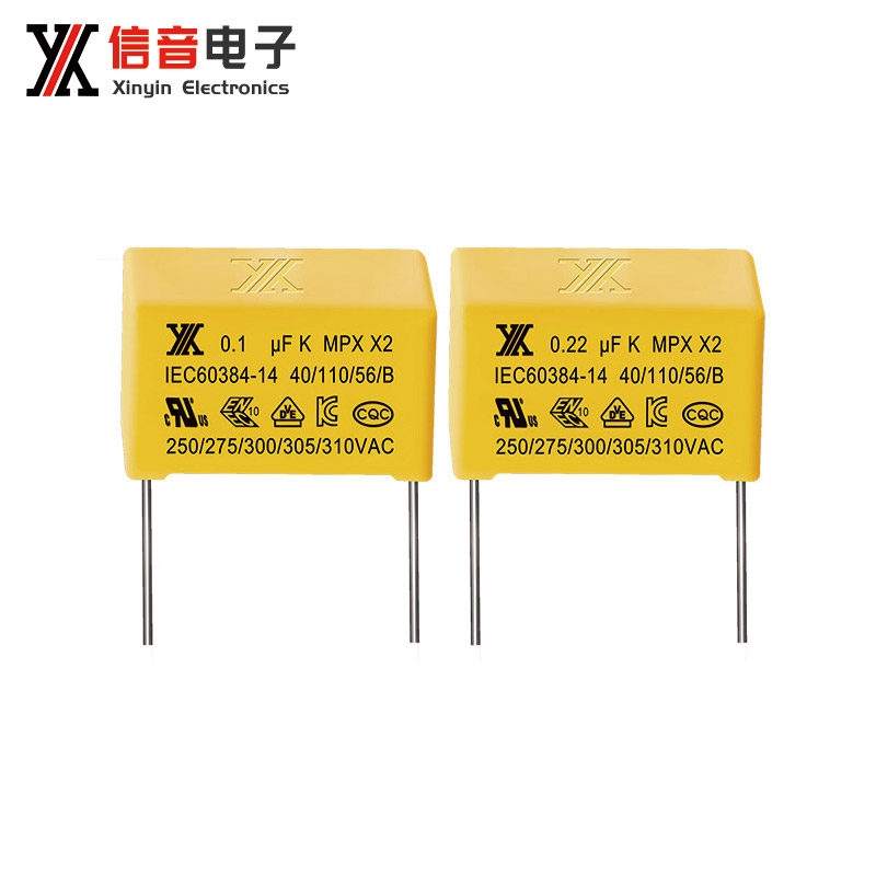


The core principle of capacitive filtering is to use the charging and discharging characteristics of capacitors to "smooth" the voltage or signal in the circuit, filter out unwanted noise components, and retain the target signal or stable power supply voltage.1. Basic working mechanism: Charge and discharge characteristics of capacitorsA capacitor can be seen as a 'temporary energy storage container':Charging process: When the voltage in the circuit is higher than the voltage across the capacitor, the capacitor will quickly store electrical energy, and the voltage across the capacitor will rise accordingly;Discharge process: When the voltage in the circuit is lower than the voltage across the capacitor, the capacitor will release the stored electrical energy to the circuit, supplementing the voltage gap in the circuit.This dynamic balance of charging and discharging can fill the voltage fluctuations and gaps, making the originally fluctuating voltage tend to stabilize.2. Filtering Logic in Different CircuitsFiltering in power circuits (most common scenario)After rectification, the output of the power supply is pulsating DC (voltage fluctuates). At this time, a capacitor can be connected in parallel in the circuit to achieve filtering:When the pulsating voltage is at its peak, the capacitor charges and absorbs excess electrical energy;When the pulsating voltage is at its valley value, the capacitor discharges and releases electrical energy to fill the voltage valley.The fluctuation amplitude of the final output voltage is significantly reduced, becoming a stable DC power, providing stable power supply for subsequent circuits.Filtering in Signal CircuitsCapacitors can be divided into high pass filtering and low-pass filtering in signal circuits, and the core is to utilize the "on-off characteristics" of capacitors for signals of different frequencies:Low pass filtering: a capacitor is connected in parallel with a resistor, allowing low-frequency signals to pass through smoothly. High frequency interference signals will be "short circuited" to ground by the capacitor, thereby filtering out high-frequency clutter and retaining low-frequency effective signals;High pass filtering: A capacitor is connected in series with a resistor, allowing high-frequency signals to be transmitted through the capacitor while low-frequency signals are blocked. It is suitable for scenarios where high-frequency signals need to be extracted.3. Key influencing factorsThe capacity of a capacitor directly determines the filtering effect:Small capacity capacitor: It has good filtering effect on high-frequency signals and is commonly used to filter out high-frequency noise in power supplies;Large capacity capacitor: Strong charging and discharging ability, suitable for handling low-frequency fluctuations in power supply, making voltage more stable. In practical applications, large and small capacity capacitors are often combined to achieve filtering effects across the entire frequency range.
12-29Knowledge
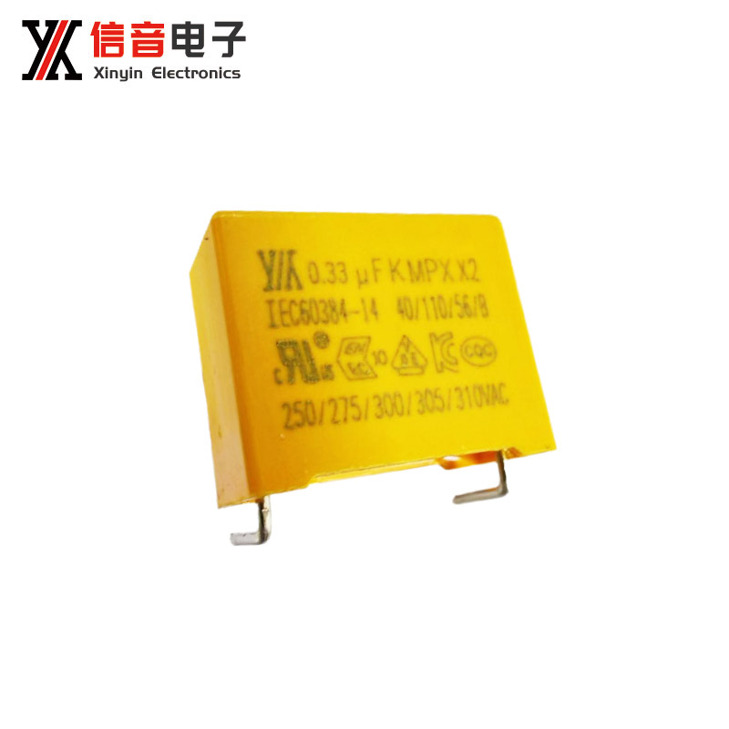
1. Principles for selecting withstand voltage valuesThe withstand voltage value is the maximum voltage upper limit that a capacitor can operate stably for a long time. When selecting, the core principle of leaving sufficient safety margin should be followed, and the following points can be referred to for details:Match the actual voltage of the circuitFirstly, clarify the peak voltage in the circuit, and the selected capacitor's withstand voltage must be higher than the maximum peak voltage of the circuit, rather than just matching the rated operating voltage. For example, in an AC circuit, the peak voltage may be higher than the effective value, and additional margin needs to be reserved.Reserve safety marginConsidering factors such as voltage fluctuations and temperature changes, it is recommended to reserve a safety margin of 20% to 50% on top of the peak voltage of the circuit. Especially in high voltage and high current scenarios such as industrial equipment and new energy, the margin needs to be appropriately increased to avoid capacitor breakdown due to instantaneous overvoltage.Adjust according to the application scenarioLow voltage scenarios such as consumer electronics: can be selected according to conventional margins;Scenarios with voltage spikes such as motor start-up and inverter circuits require further improvement in voltage withstand level;Usage in high temperature environment: The withstand voltage capability of capacitors will decrease, and it is necessary to increase the selected withstand voltage value in a targeted manner.2. Precautions for useStrictly prohibit the use of overvoltage resistanceIf the actual voltage of the circuit is close to or exceeds the withstand voltage value of the capacitor for a long time, it may cause breakdown of the capacitor dielectric, resulting in leakage, bulging, or even explosion, and may also damage other components in the circuit.Distinguish AC/DC withstand voltageSome capacitors will be labeled with alternating current withstand voltage (AC) and direct current withstand voltage (DC), and the two cannot be mixed. AC capacitors can be used in DC circuits (provided that the DC voltage does not exceed the AC withstand voltage value), but DC capacitors cannot be directly used in AC circuits.Pay attention to the influence of temperature on voltage resistanceThe withstand voltage value of capacitors will decrease with increasing temperature. In high-temperature environments, it is necessary to avoid capacitors being in a fully loaded withstand voltage state for a long time. If necessary, heat dissipation design or upgrading the withstand voltage level can be used to ensure stability.Balance between voltage resistance and capacityAmong capacitors of the same type, the higher the withstand voltage value, the larger the volume, and the capacity may be limited. When choosing, it is necessary to take into account the requirements for voltage resistance, circuit installation space, and capacity, and avoid blindly pursuing high voltage resistance, which may lead to cost and volume waste.
12-29Knowledge
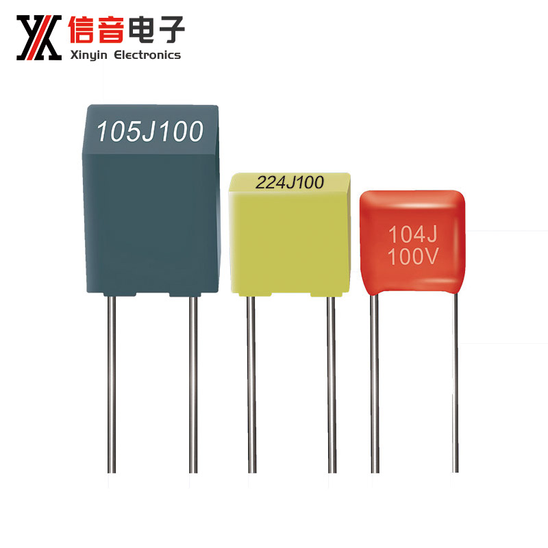
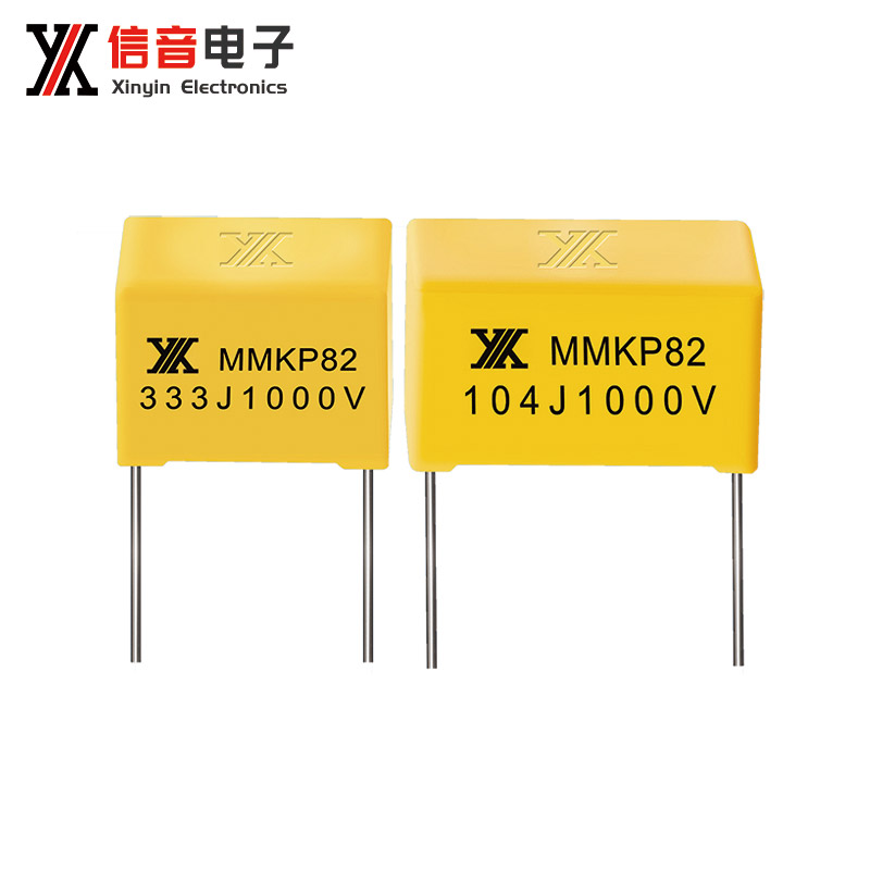
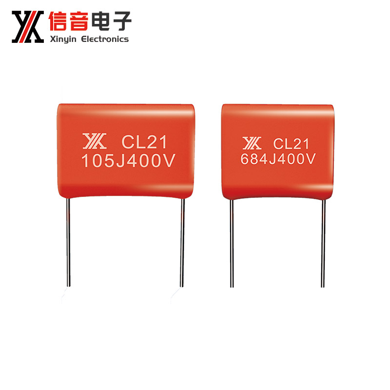
The labeling method of capacitor capacity is mainly based on the type, volume size, and application scenario design of the capacitor. Common methods include the following:Direct labeling methodDirectly labeling the capacitance value and unit on the capacitor casing is intuitive and easy to understand, commonly used for larger capacitors such as electrolytic capacitors and thin-film capacitors.For example, labeling "100 μ F", "0.1 μ F", "22pF" may also include information such as withstand voltage values and error levels.Digital annotation methodCommonly used for small capacitors (such as ceramic capacitors), it uses a three digit code * * to represent capacity, with the default unit being * * picofarads (pF) * *.The first two digits are significant figures, and the third digit is the "multiplier", indicating the number of "0s" to be added after the significant figures.For example, labeling "103" means adding 3 zeros after 10, corresponding to a capacity of 10000pF=0.01 μ F; Label "221", corresponding to a capacity of 220pF.If the third digit is "9", it means multiplying by $10 ^ {-1} $, for example, "229" corresponds to 2.2pF.Number+letter annotation methodCombining numbers and letters to represent capacity, letters can represent both the decimal point position and the unit magnitude.Letters represent decimal points: commonly seen in small capacity capacitors, such as "1n5" representing $1.5nF $and "2 μ 2" representing $2.2 μ F $(where n and μ represent nanofarads and microfarads, respectively).Letters represent magnitude: for example, "3R3" represents $3.3pF $, and the letter "R" is equivalent to a decimal point.Color code methodColor ring labeling similar to resistors, using color rings/dots of different colors to represent capacity values, errors, and withstand voltages, is commonly seen in early or small capacitors and is now less commonly used.The color of the color ring corresponds to a fixed value, and when reading, it is necessary to distinguish the starting end and calculate the capacity in order.Do you want me to help you organize a * * capacitor capacity labeling quick reference table * *, summarizing the conversion methods and examples of different labeling methods?
12-29Knowledge
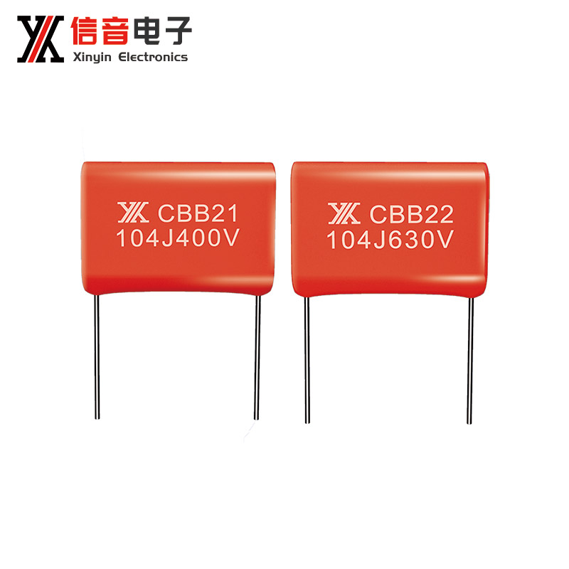
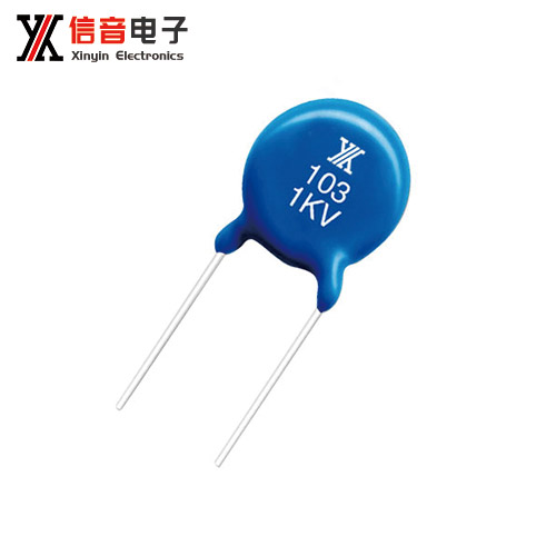
Thin film capacitors and ceramic capacitors are two widely used basic components in the electronics industry. There are significant differences between the two in terms of dielectric materials, performance characteristics, and applicable scenarios. The specific differences are as follows:Differences in dielectric materials and structuresFilm capacitors: Organic films (such as polypropylene, polyester, polystyrene, etc.) are used as dielectrics, and metal foils or metalized films are used as electrodes, which are wound and packaged to make them. According to different film materials, it can be further divided into multiple categories such as CBB (polypropylene), CL (polyester), etc.Ceramic capacitors: Using ceramic materials as dielectrics, metal paste is printed on the surface of ceramic sheets to form electrodes, which are then sintered and packaged at high temperatures. According to the characteristics of ceramic materials, they can be divided into Class I ceramic capacitors (with good temperature stability) and Class II ceramic capacitors (with large capacity and high dielectric constant).Core performance differencesCapacity range: Thin film capacitors have a wider capacity range and can achieve microfarads or even millifarads, making them suitable for scenarios with high capacity requirements; The capacity of ceramic capacitors is generally small, mainly ranging from picofarads to microfarads. The upper limit of the capacity of Class II ceramic capacitors is relatively higher, but still lower than that of thin film capacitors.Accuracy and stability: Thin film capacitors have high capacity accuracy and are less affected by temperature and voltage, resulting in excellent stability; The temperature coefficient of Class I ceramic capacitors is extremely low, and their capacity stability is comparable to that of thin film capacitors, while the capacity of Class II ceramic capacitors is greatly affected by temperature and voltage, and their stability is relatively weak.Voltage and Ripple Resistance: Thin film capacitors have stronger voltage resistance and excellent ripple current resistance, making them suitable for high voltage and high current working environments; Ceramic capacitors have relatively low withstand voltage and weak ripple resistance, making them more suitable for low voltage and low current circuits.Loss and frequency characteristics: Thin film capacitors have low dielectric loss, good high-frequency characteristics, and can maintain stable performance in high-frequency circuits; The dielectric loss of ceramic capacitors is also relatively low. Class I ceramic capacitors have excellent high-frequency characteristics and are suitable for high-frequency scenarios such as radio frequency, while Class II ceramic capacitors have slightly inferior high-frequency performance.Differences in applicable scenariosThin film capacitors: commonly used for filtering and energy storage in power circuits, reactive power compensation in motors, signal coupling in audio equipment, as well as high-voltage and high current scenarios such as new energy vehicles and charging piles.Ceramic capacitors: With their advantages of small size and low cost, they are widely used in power filtering, signal bypass, resonance matching of RF circuits, and circuits of various miniaturized electronic devices in consumer electronics such as mobile phones and computers.
12-29Knowledge
The core principle of capacitive filtering is to use the charging and discharging characteristics of capacitors to "smooth" the voltage or signal in the circuit, filter out unwanted noise components, and retain the target signal or stable power supply voltage.1. Basic working mechanism: Charge and discharge characteristics of capacitorsA capacitor can be seen as a 'temporary energy storage container':Charging process: When the voltage in the circuit is higher than the voltage across the capacitor, the capacitor will quickly store electrical energy, and the voltage across the capacitor will rise accordingly;Discharge process: When the voltage in the circuit is lower than the voltage across the capacitor, the capacitor will release the stored electrical energy to the circuit, supplementing the voltage gap in the circuit.This dynamic balance of charging and discharging can fill the voltage fluctuations and gaps, making the originally fluctuating voltage tend to stabilize.2. Filtering Logic in Different CircuitsFiltering in power circuits (most common scenario)After rectification, the output of the power supply is pulsating DC (voltage fluctuates). At this time, a capacitor can be connected in parallel in the circuit to achieve filtering:When the pulsating voltage is at its peak, the capacitor charges and absorbs excess electrical energy;When the pulsating voltage is at its valley value, the capacitor discharges and releases electrical energy to fill the voltage valley.The fluctuation amplitude of the final output voltage is significantly reduced, becoming a stable DC power, providing stable power supply for subsequent circuits.Filtering in Signal CircuitsCapacitors can be divided into high pass filtering and low-pass filtering in signal circuits, and the core is to utilize the "on-off characteristics" of capacitors for signals of different frequencies:Low pass filtering: a capacitor is connected in parallel with a resistor, allowing low-frequency signals to pass through smoothly. High frequency interference signals will be "short circuited" to ground by the capacitor, thereby filtering out high-frequency clutter and retaining low-frequency effective signals;High pass filtering: A capacitor is connected in series with a resistor, allowing high-frequency signals to be transmitted through the capacitor while low-frequency signals are blocked. It is suitable for scenarios where high-frequency signals need to be extracted.3. Key influencing factorsThe capacity of a capacitor directly determines the filtering effect:Small capacity capacitor: It has good filtering effect on high-frequency signals and is commonly used to filter out high-frequency noise in power supplies;Large capacity capacitor: Strong charging and discharging ability, suitable for handling low-frequency fluctuations in power supply, making voltage more stable. In practical applications, large and small capacity capacitors are often combined to achieve filtering effects across the entire frequency range.
12-29Knowledge
1. Principles for selecting withstand voltage valuesThe withstand voltage value is the maximum voltage upper limit that a capacitor can operate stably for a long time. When selecting, the core principle of leaving sufficient safety margin should be followed, and the following points can be referred to for details:Match the actual voltage of the circuitFirstly, clarify the peak voltage in the circuit, and the selected capacitor's withstand voltage must be higher than the maximum peak voltage of the circuit, rather than just matching the rated operating voltage. For example, in an AC circuit, the peak voltage may be higher than the effective value, and additional margin needs to be reserved.Reserve safety marginConsidering factors such as voltage fluctuations and temperature changes, it is recommended to reserve a safety margin of 20% to 50% on top of the peak voltage of the circuit. Especially in high voltage and high current scenarios such as industrial equipment and new energy, the margin needs to be appropriately increased to avoid capacitor breakdown due to instantaneous overvoltage.Adjust according to the application scenarioLow voltage scenarios such as consumer electronics: can be selected according to conventional margins;Scenarios with voltage spikes such as motor start-up and inverter circuits require further improvement in voltage withstand level;Usage in high temperature environment: The withstand voltage capability of capacitors will decrease, and it is necessary to increase the selected withstand voltage value in a targeted manner.2. Precautions for useStrictly prohibit the use of overvoltage resistanceIf the actual voltage of the circuit is close to or exceeds the withstand voltage value of the capacitor for a long time, it may cause breakdown of the capacitor dielectric, resulting in leakage, bulging, or even explosion, and may also damage other components in the circuit.Distinguish AC/DC withstand voltageSome capacitors will be labeled with alternating current withstand voltage (AC) and direct current withstand voltage (DC), and the two cannot be mixed. AC capacitors can be used in DC circuits (provided that the DC voltage does not exceed the AC withstand voltage value), but DC capacitors cannot be directly used in AC circuits.Pay attention to the influence of temperature on voltage resistanceThe withstand voltage value of capacitors will decrease with increasing temperature. In high-temperature environments, it is necessary to avoid capacitors being in a fully loaded withstand voltage state for a long time. If necessary, heat dissipation design or upgrading the withstand voltage level can be used to ensure stability.Balance between voltage resistance and capacityAmong capacitors of the same type, the higher the withstand voltage value, the larger the volume, and the capacity may be limited. When choosing, it is necessary to take into account the requirements for voltage resistance, circuit installation space, and capacity, and avoid blindly pursuing high voltage resistance, which may lead to cost and volume waste.
12-29Knowledge
The labeling method of capacitor capacity is mainly based on the type, volume size, and application scenario design of the capacitor. Common methods include the following:Direct labeling methodDirectly labeling the capacitance value and unit on the capacitor casing is intuitive and easy to understand, commonly used for larger capacitors such as electrolytic capacitors and thin-film capacitors.For example, labeling "100 μ F", "0.1 μ F", "22pF" may also include information such as withstand voltage values and error levels.Digital annotation methodCommonly used for small capacitors (such as ceramic capacitors), it uses a three digit code * * to represent capacity, with the default unit being * * picofarads (pF) * *.The first two digits are significant figures, and the third digit is the "multiplier", indicating the number of "0s" to be added after the significant figures.For example, labeling "103" means adding 3 zeros after 10, corresponding to a capacity of 10000pF=0.01 μ F; Label "221", corresponding to a capacity of 220pF.If the third digit is "9", it means multiplying by $10 ^ {-1} $, for example, "229" corresponds to 2.2pF.Number+letter annotation methodCombining numbers and letters to represent capacity, letters can represent both the decimal point position and the unit magnitude.Letters represent decimal points: commonly seen in small capacity capacitors, such as "1n5" representing $1.5nF $and "2 μ 2" representing $2.2 μ F $(where n and μ represent nanofarads and microfarads, respectively).Letters represent magnitude: for example, "3R3" represents $3.3pF $, and the letter "R" is equivalent to a decimal point.Color code methodColor ring labeling similar to resistors, using color rings/dots of different colors to represent capacity values, errors, and withstand voltages, is commonly seen in early or small capacitors and is now less commonly used.The color of the color ring corresponds to a fixed value, and when reading, it is necessary to distinguish the starting end and calculate the capacity in order.Do you want me to help you organize a * * capacitor capacity labeling quick reference table * *, summarizing the conversion methods and examples of different labeling methods?
12-29Knowledge
Copyright: Shantou Xinyin Electronic Technology Co., Ltd Support: 11400.cc
Copyright: Shantou Xinyin Electronic Technology Co., Ltd Support: 11400.cc